September 2021 - December 2021
Building an Autonomous Rover
I built this autonomous rover as a part of an Engineering Design class at the beginning of my freshmen year at UCLA. This project primarily involved using SolidWorks and Ardunio.
The Basics: ROVER I
SolidWorks and 3D Printing
Most of the students in this class, including myself, were new students who were just being introduced to SolidWorks, Arduino and other engineering equipment like laser cutters. Therefore, we initially modelled a simple rover with no autonomous functions. It simply moved using the keyboard using bluetooth, and had an ultrasonic sensor which would stop the rover from moving before it banged onto an object.
To start off with, we modelled the wheels and chassis using SolidWorks, 3D printed the wheels, and laser cut the chassis out of Acrylic. The chassis was designed with multiple holes that would allow the arduino board and 4 motors to screw onto the chassis. We were provided tire grips to ensure the wheels could move against different surfaces easily.
Electronics + Circuitry
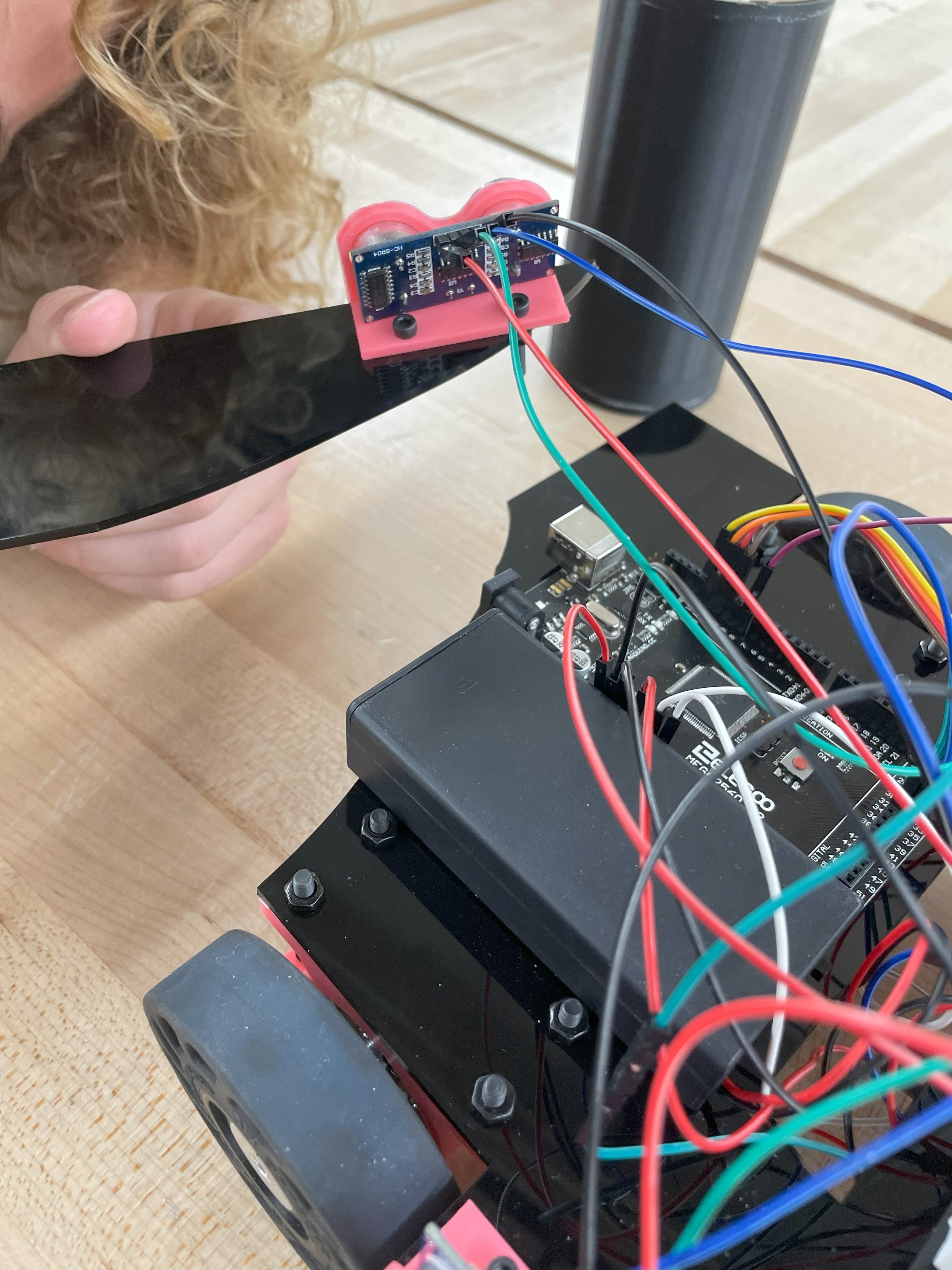
After the wheels and chassis were manufactured, we attached the wheels onto the motors, and attached onto the bottom of the chassis with screws. An ultrasonic sensor clamp was also 3D printed, and attached to the chassis with screws. The Arduino board was then attached on using screws on the top of the chassis, while the bread board was attached to the bottom with double sided tape. The wires were attached to the Arduino, Motors, and Ultrasonic sensor as shown in the diagram.
Using basic Arduino code, such as digitalWrite and digitalRead, we were able to make the rover move forward, left, right, backwards, and stop before it hit an object. The final product can be seen on the right
Using basic Arduino code, such as digitalWrite and digitalRead, we were able to make the rover move forward, left, right, backwards, and stop before it hit an object. The final product can be seen on the right
Final Project: Andre, our Autonomous Rover
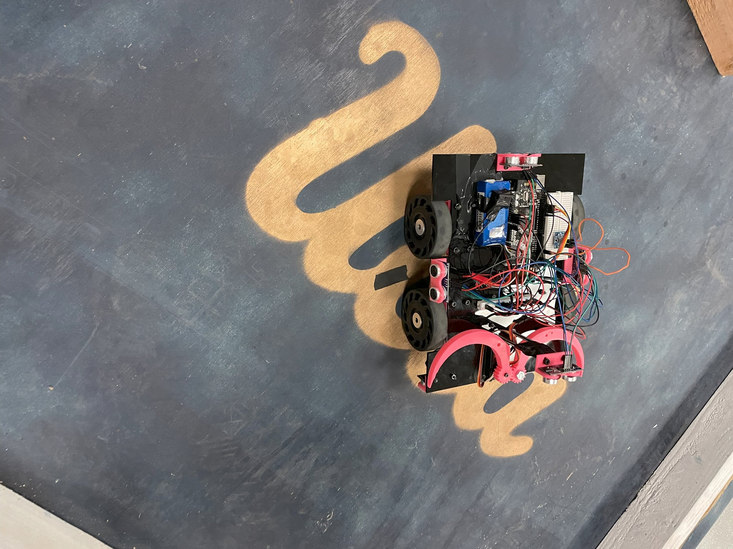
For the final project, we worked in a team of 4 to produce an autonomous rover that would be able to navigate a maze, find an object at the other end of the maze, pick it up, and drop it off at a predetermined pick-up point. We had roughly 4 weeks to complete this rover. To do this, we decided to design our rover to have 4 ultrasonic sensors: sensors on all 4 sides of the rover.
Design
The Gripper
For our gripper, we decided the easiest to print and get our rover in the testing phase would be a gripper with a single prong on either side (so it acted as a kind of chopstick). The object the rover was designed to pick up was a circular cylinder, and we figured that by slightly offsetting the prongs, we would be able to get the gripper to fully close and secure around the cylinder. We decided to add gears to either side of the gripper so we would only need to wire in a single servo motor, and we could ensure that the grippers would move in sync with each other. Using SolidWorks, we were able to fully CAD these grippers with little difficulty, and 3D print them using PLA.
The Chassis
For our chassis, we decided to go with a simple rectangular design with cut-ins for the wheels, as it would be easy to place all the ultrasonic sensors symmetrically around, and easy to CAD. To quicken the manufacturing process, we also decided to simply laser cut this chassis on acrylic. The choice of acrylic was made as our team preferred the aesthetic, but as our project progressed, we realised wood may have been a wiser choice as it was easier to modify and drill new holes in, as well as less prone to cracking under pressure, which we faced as a minor issue when running our rover multiple times for testing.
Wiring
The wiring of our rover was more or less identical to the initial rover, with the Bluetooth module included, except for the addition of more ultrasonic sensors. For the Arduino code of our rover, we coded the rover so that when the ultrasonic sensor detected an object roughly 10 cm away from it, it would rotate in small increments until it found a position in which none of the ultrasonic sensors were blocked, and move forward, repeating this process until it navigated through the maze.
Challenges
With the manipulator, our gripper was initially built to be in level with each other, though we realised this prevented the gripper from properly closing fully. We solved this by deciding to slightly offset the prongs from each other, and due to time constraints, used screws and bolts to achieve this off set in a secure manner. Furthermore, our measurements of where the grippers should be mounted on the chassis (and hence where the holes were) was slightly off, meaning the gears didn't initially work properly as there wasn't enough contact for the to move with each other, and due to time constraints, and material constraints, we were not able to create another chassis. To solve this, we used elastic bands that slightly angled the screws that mounted the gripper arms onto the motor and chassis together, so that there was better contact between the gears. This allowed the gripper to work effectively as planned. Our gripper also got in the way of our initial positioning of the ultrasonic sensor, as we realised after multiple trials that with our initial mounting of the ultrasonic sensor landed up with our ultrasonic sensor detecting the sensor, which affected its ability to move autonomously. This had occured as we had initially assumed that the ultrasonic sensor would only detect objects within the diamater of the sensor (in more of a laser kind of focus), however, in reality the sensor detected things slightly below and above it as well (in more of a conical width of vision), hence it was able to see the ultrasonic sensor. Within our object, we were bale to find longer pieces of screws that along side several bolts and the help of adhesives like duct tape, we were able to build a longer mounting piece for the ultrasonic sensor that was very secure (even more so than our initially 3D printed mounting device). We decided to opt for this instead of a longer 3D printed mounting tower, as it used less materials, and ended up being probably stronger, as the tower we would build would have had to be hollow and have a whole underneath it, otherwise it would have interfered with mechanisms such as the gripper.
During the final week of our project, our chassis also snapped due to our choice of material, acrylic, being rather brittle. This happened when our rover was momentarily triggered while still plugged into our laptop, resulting in the front of the rover moving while the back was held back by the laptop, and while this alone would not have snapped the chassis, the stress that the chassis faced over the last weeks of testing while carrying 4 motors, an arduino, 4 ultrasonic sensor, a gripper, screws, and more, had resulted in the chassis bending and weakening. Hence, with these factors combined, our chassis snapped. Luckily, the point of breakage was not at any position where any significant components (like the arduino, motors or gripper) was removed. The breakage almost removed the back ultrasonic sensor( as half of the ultrasonic sensor was hanging off), however with the use of superglue and duct tape (temporary fixes that we had available for us at the time with only under a few more days left on the project) were available. With this, it was able to hold till the final day of the project.
Final Video + Conclusion
This Autonomous rover project was the first project I participated in at UCLA, during my first quarter here. It is where I initially learned how to use SolidWorks, where I first ever used an Arduino, and learned basic manufacturing techniques like laser cutting and 3D printing. If I were to do this project again, I would improve it by using sturdier materials for the chassis, like wood. I would have also like to have improved our gripper design by building more of a claw like structure, so it would be able to grip onto more objects more steadily. I would also extend the project further by learning how to use MATLAB to build a mapping feature for the rover.
However, with more time, or in the future, I would consider using a more durable material such as wood, and try and reduce the forces on the rover by using only 2 motors, and using an axle to connect the wheels instead. I would also consider mounting the arduino slightly more towards the back to better balance out the masses on the rover, as the front held the gripper and its mounting, as well as the ultrasonic sensor, while the back only had the single ultrasonic sensor. Because of this final crack on the last week of the project, we also decided to name our rover Andre, after the St. Andreas fault line.
With a higher budget, it would have been nice to use better ultrasonic sensors and motors. The sensors we had access to were cheap and previously used sensors that often had random reading values that we would have to account for in our code by including delays and having the code only consider values as being true if it was read several times within the same range of values directly before and after it. They stopped working several times during the week, reading 0 values when not covered, or producing random values, and the only fix for this was to replace them. With better ultrasonic sensors, this would have saved us a lot of time and troubleshooting when wondering whether our rover failed working because of code errors, mechanical set up errors, or simply equipment and ultrasonic sensor errors. Furthermore, our rover ended up being a lot slower than we desired as our motors were not the most powerful, and died several times. During the final day, all of our motors stopped working, one after the other, and we had to rewire each of them with new motors, which were even less powerful and hence even slower. With more powerful motors that didn't die as often, we would have saved time, and would be able to have a rover that could finish the task we got in much quicker speeds.


